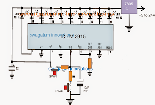
This specific circuit works extremely well for changing an LED bar graph in the
" up " pattern or down order by having a two press button switches. The idea
could be enforced for several other handy purposes.
In most circuit
apps we require a electronically run control system permitting an upward or
downward control of a precise parameter, like for prevailing heat, sound volume,
PWM, motor speed etc.
The application may well seem simple however
putting into action it almost is probably not that simple, until specific (rare
to find) ICs are involved.
Right here we are going to see the identical
would possibly be achieved with the aid of the IC LM3915 that is certainly
really often readily available globally and is particularly moderately
affordable.
Knowing the recommended up/down LED series controller circuit implementing push button is extremely effortless, and might be achieved just by discussing these figure.
The image exhibits a LM3915 LED bar graph driver IC, constructed in its conventional form.
Ten LEDs can be found attached throughout the ten outputs from the ICs.
The LEDs work to illumine one behind the several other within a straight pattern by pin#1 to pin#10 of the IC, according to a rising potential across its pin#5, that means provided that the potential at pin#5 is zero, every one of the LEDs could be presumed to generally be powered down, so that as the potential at pin#5 is increased, the LEDs might be noticed enlightening sequentially right from pin#1 right up until pin#10.
Pin#10 LED shows if the potential at pin#5 actually reaches about 2.2V.
The sequencing from the LEDs may be from the dot mode (if pin#9 is open) or maybe during the bar mode (when pin#9 will be associated with the positive supply).
In the above design considering that the pin#9 will not be put to use or is actually unconnected, the sequencing in the LEDs are located in the dot mode, signifying only one LED will be lit any kind of time instantaneous along the specific pinout from the IC.
Pertaining to utilizing the up or down sequence, SW#1 or SW#2 is required to be step by step pressed.
Anytime SW#2 is pressed, the capacitor across pin#5 on the IC is are actually get rid of gently, evoking the potential to decrease steadily until finally may be it reaches 0V.
According to this the LED series could be found "running" in the opposite direction" from pin#10 to pin#1.
Alternatively while SW#1 is pressed, the 10uF capacitor can be are usually acquire charged progressively which often encourages the IC outputs to promote the LED sequencing from pin#1 towards pin#10.
Hence the two push buttons can be adequately pressed and released for acquiring any one preferred pinout of the IC to be in the active status, dependant on the charge level of the pin#5 capacitor.
The actual concept might be executed for numerous other identical purposes merely by establishing the control stage along with the different pinouts of the IC in the expected pattern.

No comments:
Post a Comment