In this post we learn the microwave sensor IC KMY 24 and make sure to recognize its properties and its pinout achievement information.
The KMY24 microwave sensor module was created and developed on the idea of Doppler impact. When properly set up it radiates a reduced power microwave signal of around 2.45 GHz across the instructed area.
When an object (affect) that may be actually a human being, is available in the range of the provided signal, the signals obtain mirrored returning to the sensor module with certain interference pertaining to the original frequency, this really is generally referred to as the Doppler shift.
The moment this mirrored frequency shift is found by the sensor, the in built circuitry immediately combines the mirrored frequency with the present original frequency and generates two individual frequencies across its stipulated outputs.
According to the concepts of Doppler impact this frequency stage shift might be possibly positive or negative based upon whether the object in the sensor area was receding or getting in touch with the sensor.
The performance of the KMY24 concludes here, along with the outputs from the device now is required to be amplified by means of appropriate voltage amplifier configuration, for instance by means of an differential opamp amplifier circuit etc.
Additional on the opamp output might be effectively closed with a relay phase or a recorder or an alarm for distinguishing or recognizing the felt guidelines.
The properties of the IC KMY24 might be discovered given below:
High sensitivity and identification even if a comparatively smaller target approaches the zone.
Twin mixer circuitry for making it possible for directional movement detection of the target
High dependability for accomplishing fool proof outcomes
Rare power consumption which makes it completely recommended for battery operated functions.
Minimal harmonic emission for decreased RF disruption in the environment.
Compact size.
The following image demonstrates the pinout information of the KMY 24 microwave sensor
KMY 24 Microwave Sensor pinout details

The subsequent image offers the breakdown guidelines or the definite maximum voltage and current ratings that should be put on to the IC, these types of guidelines should not be exceeded, to be accurate these types of has to be stored nicely below the demonstrated values.

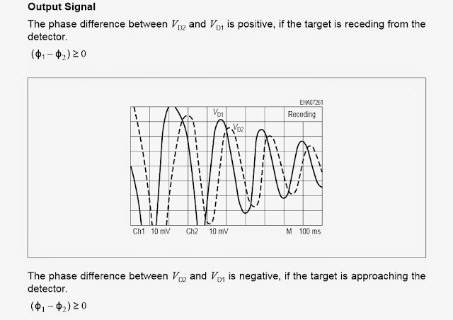
The two images demonstrated below illustrate the phase shift or the difference in the position of the reflected frequency pertaining to the original radiated frequency when the target is getting in touch with (first image below), just as soon as the target is receding or returning (the second diagram below).

KMY 24 Microwave Sensor frequency activates when target is getting in touch with
KMY 24 Microwave Sensor frequency activates when target is receding
Over the following (coming) article we are going to make sure to recognize concerning easy methods to use a microwave sensor by means of a reasonable circuit.
The KMY24 microwave sensor module was created and developed on the idea of Doppler impact. When properly set up it radiates a reduced power microwave signal of around 2.45 GHz across the instructed area.
When an object (affect) that may be actually a human being, is available in the range of the provided signal, the signals obtain mirrored returning to the sensor module with certain interference pertaining to the original frequency, this really is generally referred to as the Doppler shift.
The moment this mirrored frequency shift is found by the sensor, the in built circuitry immediately combines the mirrored frequency with the present original frequency and generates two individual frequencies across its stipulated outputs.
According to the concepts of Doppler impact this frequency stage shift might be possibly positive or negative based upon whether the object in the sensor area was receding or getting in touch with the sensor.
The performance of the KMY24 concludes here, along with the outputs from the device now is required to be amplified by means of appropriate voltage amplifier configuration, for instance by means of an differential opamp amplifier circuit etc.
Additional on the opamp output might be effectively closed with a relay phase or a recorder or an alarm for distinguishing or recognizing the felt guidelines.
The properties of the IC KMY24 might be discovered given below:
High sensitivity and identification even if a comparatively smaller target approaches the zone.
Twin mixer circuitry for making it possible for directional movement detection of the target
High dependability for accomplishing fool proof outcomes
Rare power consumption which makes it completely recommended for battery operated functions.
Minimal harmonic emission for decreased RF disruption in the environment.
Compact size.
The following image demonstrates the pinout information of the KMY 24 microwave sensor
KMY 24 Microwave Sensor pinout details
The subsequent image offers the breakdown guidelines or the definite maximum voltage and current ratings that should be put on to the IC, these types of guidelines should not be exceeded, to be accurate these types of has to be stored nicely below the demonstrated values.
The two images demonstrated below illustrate the phase shift or the difference in the position of the reflected frequency pertaining to the original radiated frequency when the target is getting in touch with (first image below), just as soon as the target is receding or returning (the second diagram below).
KMY 24 Microwave Sensor frequency activates when target is getting in touch with
KMY 24 Microwave Sensor frequency activates when target is receding
Over the following (coming) article we are going to make sure to recognize concerning easy methods to use a microwave sensor by means of a reasonable circuit.
No comments:
Post a Comment