In this particular post we are going to find out about a basic circuit that enables a manual change characteristic for the glow timing of a motorcycle's CDI often to accomplish an progress ignition, retarded ignition or simply a standard timed ignitions.
After an extensive research relating to the topic I had been apparently effective in developing this circuit which could be utilized by any motorcycle rider for attaining improved speed and fuel effectiveness by adjusting the ignition timing of the vehicle's engine as preferred, determined by its immediate speed.
Everyone knows that the timing of the ignition spark produced inside a vehicle engine is vital relating to its fuel effectiveness, engine life along with the speed of the vehicle, incorrectly timed CDI sparks can create a badly functioning vehicle and vice versa.
The suggested igniting valuable time for the spark inside the combustion chamber is when the piston is all about 10 degrees after it has crossed the TDC (Top Dead Center) point. The obtain coil is tuned to correspond this and each and every time the piston gets to right before the TDC, the pickup coil causes the CDI coil to fire the spark, referred to as BTDC (before top dead .
The combustion handled the above method usually generates a good engine working and also emissions.
In spite of this the above functions perfectly merely so long as the engine is functioning at certain suggested average speed, however for motorcycles that hopefully will achieve amazing speeds the above concept begins malfunctioning along with the motorcycle is inhibited from attaining the stipulated high speeds.
Such things happen simply because at higher speeds the piston moves much quickly compared to the ignition spark may foresee it. Even though the CDI circuit is linked to the activating properly, and attempts to match the piston place, once the spark has the capacity to start up at the spark plug, the piston possesses already traveled much in front of the TDC, leading to unwanted combustion situation for the engine, which often causes inefficiencies, stopping the engine from getting its specific higher speed limitations.
Consequently to be able to correct the ignition firing time, we have to somewhat progress the spark plug firing by instructing somewhat innovative trigger for the CDI circuit, and for less quickly speeds this basically must be changed along with the firing must be essentially somewhat retarded for enabling optimum effectiveness for the vehicle engine.
We are going to talk about all these guidelines much elaborately in various other article, currently we may wish to examine the technique that is going to permit us to attain a manual adjustments of the ignition spark timing either to progress, retard or work usually according to the speed of the motor bike.
From the above conversation we are able to finalize that the pickup coil cause will not exclusively turn out to be dependable for high speed motorcycles, as well as some technique of improving the pickup signal turns into crucial.
Usually this is achieved utilizing microcontrollers, I have attempted to attain the identical utilizing normal parts, it seems that it seems to be a logically possible design, even though merely a practical test can verify it's functionality.
Adjustabe CDI Spark Advance/Retard Circuit for Motorcycles
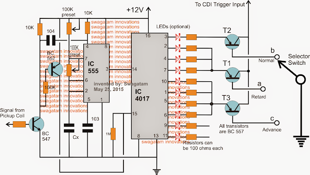
Talking about the above design of the offered adjustable CDI spark advance and retard timer circuit, we are able to notice a regular IC 555 and an IC 4017 circuit that happen to be rigged in a regular "LED chaser light circuit" mode.
The IC 555 is placed similar to an astable that generates and feeds clock pulses to pin#14 of the IC 4017 which often replies to these types of pulses and delivers an "jumping" high logic across its output pinouts beginning with pin#3 to pin#11 after which go back to pin#3.
A few NPN/PNP BJTs can be viewed on the left side of the diagram, these are generally placed to reset the two ICs in accordance with the signals received from the motorcycles pickup coil.
The pickup coil signal is fed to the base of the NPN which encourages the ICs to reset and restart the oscillations, each and every time the pickup coil sustains a finished innovation by the related flywheel.
Currently, the IC 555 regularity is adjusted such that once the pickup coil picks up one innovation and resets the ICs, the 555 IC has the capacity to generates about 9 to 10 pulses allowing the IC 4017 to make a high upto its pin#11 or at least upto its pinout#9.
The above might be set for revolutions matching the idling speed of the motorcycle.
This implies that throughout idle speeds the pickup coil signals will allow the 4017 outputs to travel by means of just about all the pinouts until its reset back to pin#3.
In spite of this, now let's make sure to imitate exactly what would certainly occurs at higher speeds.
At higher speeds the pickup signals might generate quicker signals compared to the normal setting, knowing that might consequently reduce the IC 555 from producing the required 10 pulses, so could be right now it might be in a position to produce say around 7 pulses or 6 pulses at a particular higher speed of the vehicle.
Consequently might reduce the IC 4017 from allowing almost all its output to be high, rather now it might be capable of perform only for as long as pin#6 or pin#5, after which the pickup would certainly force the IC to reset.
From the above conversation we are able to simulate a scenario where at idle speeds, the outputs of the 4017 IC is dividing the pickup flywheel rotation into 10 divisions, in which the bottom 3 or 4 pinout signals may be widely known as matching the signals that could be happening right before the real pickup coil initiating signal, likewise the pinout high logics at pin#2,4,7 could possibly be simulated to be the signals showing up right after the real pickup coil initiating has progressed past.
Consequently we are able to believe the signals at the lower pinouts of the IC 4017 to be "advancing" the real pickup signals. Additionally, because the resetting from the pickup places the IC 4017 high to its pin#3, this pinout may be thought to be related the pickup's normal "recommended" trigger....while the pinouts that follow the pin#3, which is the pinouts2,4,7 could possibly be believed to be the signals corresponding to the late signals or the "retarded" signals, with regards to the real pickup causes.
How you can Establish the Circuit
For this purpose we first require to learn the time required by the pickup signal to produce each alternate pulses.
Think you record it to be around 100 millisecond (an arbitrary value), this could suggest that the 555 IC has to generate pulses at its pin#3 at the rate of 100/9 = 11.11 ms.
As soon as this is set, we are able to approximately believe the outputs from the 4017 to be creating high logic across all its outputs which might slowly "recede" as the pickup signals become quicker and quicker as a reaction to the vehicle's speed.
This could certainly stimulate a receding "high" logics across the bottom pinouts of the IC 4017, consequently at higher speeds the rider would certainly obtain a choice of manually resorting to the lower sets of pins for initiating the CDI coil, as demonstrated in the diagram (notice selector switch choices).
In the figure we are able to notice a selector switch that can be used for choosing the pinout causes from the IC 4017 IC for activating the CDI coil.
As described above, the lower group of receding pinout high logics once chosen, will allow an progress initiating of the CDI coil therefore permit the rider to attain a self adjusting automatic advance firing of the CDI coil, but yet this has to be chosen only after the vehicle is functioning much above the suggested normal speed.
Exactly the same if the rider contemplates a lower speed for the vehicle, he can toggle the switch for choosing the "retarded" timing choice, offered across the pinouts which are soon after the pin#3 of the IC 4017.
Throughout the suggested normal speeds the biker can choose the pin#3 as the initiating output for the CDI which might permit the vehicle to enjoy an effective ride at the presented normal speeds.
In the next article we'll make sure to examine a circuit that might make it possible for the above advance and retard timing of the sparks instantly without the riders involvement to be able to make sure optimum effectiveness throughout the various speed levels of the motorcycle.
No comments:
Post a Comment