In the revealed SMD solar LED light circuit above, we understand the following steps:
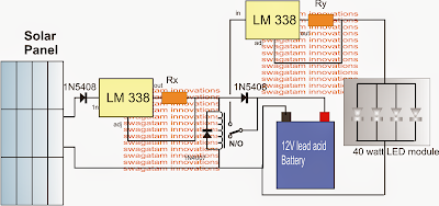
A solar panel
A number of current controlled LM338 regulator circuits
A changeover relay
A rechargeable battery
and a 40 watt LED SMD module
The above levels are integrated in the following discussed technique:
The two LM 338 levels are connected in usual current regulator modes with choosing the particular current sensing resistances for making sure a current controlled output for the related associated load.
The load for the left LM338 is the battery which happens to be charged derived from this LM338 step in addition to a solar panel input source. The resistor Rx is measured this sort of that the battery acquires the mentioned level of current as well as being not over driven or over charged.
The right side LM 338 is made up of the LED module and here too the Ry confirms that module will come in with the appropriate particular quantity of current with the intention to preserve the devices from a thermal runaway condition.
The solar panel voltage features could be somewhere between 18V and 24V.
A relay is presented in the circuit it is wired with the LED module such that it's activated just during the nighttime or when it's dark below threshold for the solar panel to create the preferred any kind of power.
As far as the solar voltage is obtainable, the relay continues energized isolating the LED module from the battery and making sure that the 40 watt LED module remains to be closed off at the time of day time and even while the battery is getting charged.
After dusk, when the solar voltage evolves into satisfactorily low, the relay will no longer be capable to maintain its N/O position and flips to the N/C changeover, connecting the battery with the LED module, and illuminating the array by way of the accessible entirely charged battery power.
The LED module can be viewed linked to a heatsink which need to be sufficiently huge that allows you to arrive at an optimal benefit from the module and for providing longer life span and brightness from the device.
The suggested reducing resistors could be measured from the provided formulas:
Rx = 1.25/battery charging current
Ry = 1.25/LED current rating.
Considering the battery to be a 40 AH lead acid battery, the desired charging current needs to be 4 amps.
for that reason Rx = 1.25/4 = 0.31 ohms
wattage = 1.25 x 4 = 5 watts
The LED current is available by separating its total wattage by the voltage rating, that is definitely 40/12 = 3.3amps
for that reason Ry = 1.25/3 = 0.4 ohms
wattage = 1.25 x 3 = 3.75 watts or 4 watts.
Reducing resistors are not useful for the 10 watt LEDs due to the fact the input voltage from the battery is equal to the particular 12V limit of the LED module thereby are unable to go beyond the protected boundaries.
No comments:
Post a Comment