Even though the above designs are extremely useful, all these could be considered moderately low tech with their method.
In this post we'll observe how the procedure may be executed utilizing a very much sophisticated PWM based motor soft start controller circuit.
The concept here is to apply a step by step incrementing PWM to a motor every time it's activated, this action enables the motor to attain a linearly expanding speed from zero to maximum within a required interval, which can be variable.
PWM generator circuit for applying soft start in motors, and pumps

With reference to the figure above, the production of the linearly incrementing PWM is achieved with the aid of two 555 IC, configured in their normal PWM mode.
I have previously discussed the concept elaborately in one of my earlier articles explaining how to use IC 555 for developing PWM.
As could be observed in the diagram, the design employs two 555 ICs, IC1 becoming wired prefer as astable, while IC2 as a comparator.
IC1 produces the needed clock signals at a given frequency (dependent upon the values of R1 and C2) that could be put on to pin#2 of the IC2.
IC2 utilizes the clock signal to obtain triangle waves across its pin#7, to ensure that these types of may be compared with the potential available from its control voltage pin#5.
Pin#5 receives the preferred control voltage through an NPN emitter follower stage made with the support of T2 along with the associated components.
Whenever power is switched ON, T2 is fed with a ramping or a gradually increasing voltage at its base via R9, and also due to the the proportionate charging of C5.
This ramping potential is appropriately duplicated across the emitter of T2 with respect to the supply voltage at its collector, which means the base data is modified into a steadily increasing potential starting from zero to almost the supply voltage level.
This ramping voltage at pin#5 of IC 2 is immediately as compared to available triangle wave across pin#7 of IC2, which is certainly translated into a linearly incrementing PWM at pin#3 of IC2.
The linearly incrementing process of the PWMs occurs until C5 is completely charged and the base of T2 reaches a stable voltage level.
The above design looks after the PWM generation whenever power is activated.
In order to implement the PWM soft start result, the output from pin#3 of IC2 is required to be applied to a triac power driver circuit, since shown below:

The above image shows how the switch ON soft start PWM control could be executed on heavy motors for the expected goal.
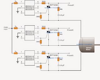
In the figure above we see how triac driver isolators with zero crossing detector can be utilized for driving the motors with the linearly incrementing PWMs for accomplishing a soft start impact.
The above process effectually deals with the start ON overcurrent situating on single phase motors.
However should a 3 phase motor is employed, the following concept can be used for executing the suggested 3 phase soft start on motors.
No comments:
Post a Comment