The submit describes a basic boost converter UPS circuit for providing an uninterruptible power to satellite TV set top boxes to ensure that the offline recording is rarely permitted to fail in the course of power outages.
I had considered a small back up system,
I had acquired a small 6 volt 11 watt CFL Ballast circuit considering as inexpensive alternate solution, but the same failed to work.
Why I am looking for AC supply as opposed to DC?
I do not wish to tamper with their system and get penalized for in any way problems which can arrive at it as a result of natural process procedure.
Could you please assist me with a relatively easy economical circuit which will provide me 220 volt 20 watts power from 6 volt 5ah battery. To be accurate 220 volts from 6 volt battery, as I have acquired a 6 volt 5 ah battery recently. The output wattage necessity is much less than 20 watts, the adapter ratings are:
Output - 16 volt 1 amp
Input - 240 volt.06 amp
The Design
6V to 220V Boost UPS Circuit for Satellite TV Modems
Considering that these days all electronic systems implement an SMPS power supply, the input is not going to necessarily ought to be an AC for operating these types of equipment, somewhat an equivalent DC or pulsed DC also turn out to be helpful and functions nearly as good.
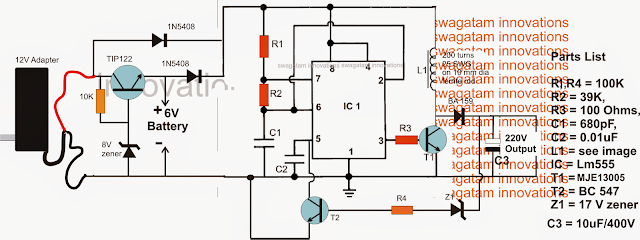
Talking about the diagram above, several parts may be seen, the IC1 design allows a 6V DC to be improved to considerably more 220V pulsed DC by means of a boost converter topology utilizing the IC 555 in its astable form. The extreme left side battery section guarantees an changeover from mains to battery back up every time a power failure is felt by the circuit.
The concept is rather easy and will not need much of an elaboration.
IC1 is set up as an astable oscillator, which drives T1 along with L1 at the same frequency.
T1 encourages the whole battery current across L1, leading to a consequently boosted voltage to emerge across it throughout the OFF periods of the T1 (induced back EMF from L1).
L1 needs to be properly determined such that it produces the essential magnitude of voltage across the proven terminals.
The mentioned 200 turns is tentatively discovered and need to have significantly tweaking for accomplishing the meant 220V from the input 6V battery source.
T2 is launched for regulating the output voltage to the preferred safe levels, which is 220V here.
Z1 ought to be consequently a 220V zener, which performs only after this limit is surpassed, which causes T2 to perform and ground pin5 of the IC, stalling the frequency at pin3 to a zero voltage.
The above procedure constantly readjusts itself quickly making sure a continuing 220V at the output.
The adapter which is often observed at the extreme left can be used for two causes, first to make sure that IC1 functions constantly and generates the needed 220V for the attached load irrespective of the mains occurrence (in the same way we certainly have in online UPS systems), as well as to make sure a charging current for the battery when mains voltage exists.
The connected TIP122 transistor is located to produce a managed 7V DC for the battery as well as to control over charging of the battery.
I had considered a small back up system,
I had acquired a small 6 volt 11 watt CFL Ballast circuit considering as inexpensive alternate solution, but the same failed to work.
Why I am looking for AC supply as opposed to DC?
I do not wish to tamper with their system and get penalized for in any way problems which can arrive at it as a result of natural process procedure.
Could you please assist me with a relatively easy economical circuit which will provide me 220 volt 20 watts power from 6 volt 5ah battery. To be accurate 220 volts from 6 volt battery, as I have acquired a 6 volt 5 ah battery recently. The output wattage necessity is much less than 20 watts, the adapter ratings are:
Output - 16 volt 1 amp
Input - 240 volt.06 amp
The Design
6V to 220V Boost UPS Circuit for Satellite TV Modems
Considering that these days all electronic systems implement an SMPS power supply, the input is not going to necessarily ought to be an AC for operating these types of equipment, somewhat an equivalent DC or pulsed DC also turn out to be helpful and functions nearly as good.
Talking about the diagram above, several parts may be seen, the IC1 design allows a 6V DC to be improved to considerably more 220V pulsed DC by means of a boost converter topology utilizing the IC 555 in its astable form. The extreme left side battery section guarantees an changeover from mains to battery back up every time a power failure is felt by the circuit.
The concept is rather easy and will not need much of an elaboration.
IC1 is set up as an astable oscillator, which drives T1 along with L1 at the same frequency.
T1 encourages the whole battery current across L1, leading to a consequently boosted voltage to emerge across it throughout the OFF periods of the T1 (induced back EMF from L1).
L1 needs to be properly determined such that it produces the essential magnitude of voltage across the proven terminals.
The mentioned 200 turns is tentatively discovered and need to have significantly tweaking for accomplishing the meant 220V from the input 6V battery source.
T2 is launched for regulating the output voltage to the preferred safe levels, which is 220V here.
Z1 ought to be consequently a 220V zener, which performs only after this limit is surpassed, which causes T2 to perform and ground pin5 of the IC, stalling the frequency at pin3 to a zero voltage.
The above procedure constantly readjusts itself quickly making sure a continuing 220V at the output.
The adapter which is often observed at the extreme left can be used for two causes, first to make sure that IC1 functions constantly and generates the needed 220V for the attached load irrespective of the mains occurrence (in the same way we certainly have in online UPS systems), as well as to make sure a charging current for the battery when mains voltage exists.
The connected TIP122 transistor is located to produce a managed 7V DC for the battery as well as to control over charging of the battery.
No comments:
Post a Comment