Talking about the following drawn 12v motor current control schematics, the idea definitely seems to be right, nevertheless the circuit achievement particularly in the second diagram appears inaccurate.
Let's examine the diagrams one at a time:


The first diagram describes the simple current control stage calculations applying an opamp and a couple of passive parts, and it appears terrific.
As mentioned in the diagram so long as V1 - V2 is lower than 0.7V, the output of the opamp ought to be zero, and the instance it touches above the 0.7V, the output ought to proceed high, even though this could use a PNP transistor at the output, not with an NPN,....anyway let's proceed.
Here the 0.7V is with reference to the diode connected to one of the inputs of the opamp, along with the concept is merely to make sure that the voltage during this pin surpasses the 0.7V limit with the intention that this pinout potential crosses the other complementing input pin of the opamp which results in a turn off trigger to be produced for the connected motor driver transistor (an NPN transistor as desired in the design)
In spite of this in the second diagram, this problem is not going to acquire executed, as a matter of fact the circuit is not going to react in any way, let's notice exactly why.
In the second diagram when power is turned on, both the input pins linked across the 0.1 ohm resistor is going to be exposed to nearly an equal quantity of voltage, but since the non-inverting pin has a dropping diode it will obtain a potential that could be 0.7V less than the inverting pin2 of the IC.
This will likely lead to the (+) input obtaining a shade lower voltage than the (-) pin of the IC, which often will supply a zero potential at pin6 of the IC right at the onset. With a zero volts at the output the linked NPN will certainly simply refuse to start along with the motor will stay turned OFF.
With the motor shut off right now there won't be any specific current attracted by the circuit and no potential impact produced across the sensing resistor. Consequently the circuit will remain inactive with absolutely nothing occurring.
There is certainly an additional mistake in the second diagram, the motor in question will have to be linked across the collector along with the positive of the transistor for creating the circuit useful, here a relay does not have any role, and is for that reason not needed.
The defective circumstance mentioned above may be reverted simply by swapping the suggestions pinouts of the IC across the mentioned factors, which is across the sensing resistors, as demonstrated in the resolved third diagram.
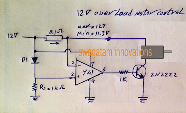
Talking about the third diagram the moment power is turned on, pin2 is going to be exposed to a 0.7V much less potential than pin3 of the IC, forcing the output to go high at the onset.
With the output going high triggers the motor to begin and acquire speed, and in case the motor attempts to obtain a current more the the specific value, the equivalent amount potential improvement will likely be produced across the 0.1 ohm resistor, now since this potential commences increasing pin3 will begin going through a falling potential, then when it drops below the pin2 potential, the output will begin to return to zero disrupting the base drive for the transistor and switching off the motor immediately.
With the motor turned OFF throughout that instant, the potential across the pins are going to tend to be normalized and will bring back back to the original condition, which often will turn on the motor and the circumstance could keep self-adjusting by means of a swift ON/OFF of the driver transistor, sustaining a proper current control over the motor.
The sensing resistor might be determined given below:
R = 0.7/current
Right here as stipulated for a 0.7amp current limit for the motor the value of the current sensor resistor R ought to be
R = 0.7/0.7 = 1 ohm
Let's examine the diagrams one at a time:
The first diagram describes the simple current control stage calculations applying an opamp and a couple of passive parts, and it appears terrific.
As mentioned in the diagram so long as V1 - V2 is lower than 0.7V, the output of the opamp ought to be zero, and the instance it touches above the 0.7V, the output ought to proceed high, even though this could use a PNP transistor at the output, not with an NPN,....anyway let's proceed.
Here the 0.7V is with reference to the diode connected to one of the inputs of the opamp, along with the concept is merely to make sure that the voltage during this pin surpasses the 0.7V limit with the intention that this pinout potential crosses the other complementing input pin of the opamp which results in a turn off trigger to be produced for the connected motor driver transistor (an NPN transistor as desired in the design)
In spite of this in the second diagram, this problem is not going to acquire executed, as a matter of fact the circuit is not going to react in any way, let's notice exactly why.
In the second diagram when power is turned on, both the input pins linked across the 0.1 ohm resistor is going to be exposed to nearly an equal quantity of voltage, but since the non-inverting pin has a dropping diode it will obtain a potential that could be 0.7V less than the inverting pin2 of the IC.
This will likely lead to the (+) input obtaining a shade lower voltage than the (-) pin of the IC, which often will supply a zero potential at pin6 of the IC right at the onset. With a zero volts at the output the linked NPN will certainly simply refuse to start along with the motor will stay turned OFF.
With the motor shut off right now there won't be any specific current attracted by the circuit and no potential impact produced across the sensing resistor. Consequently the circuit will remain inactive with absolutely nothing occurring.
There is certainly an additional mistake in the second diagram, the motor in question will have to be linked across the collector along with the positive of the transistor for creating the circuit useful, here a relay does not have any role, and is for that reason not needed.
The defective circumstance mentioned above may be reverted simply by swapping the suggestions pinouts of the IC across the mentioned factors, which is across the sensing resistors, as demonstrated in the resolved third diagram.
Talking about the third diagram the moment power is turned on, pin2 is going to be exposed to a 0.7V much less potential than pin3 of the IC, forcing the output to go high at the onset.
With the output going high triggers the motor to begin and acquire speed, and in case the motor attempts to obtain a current more the the specific value, the equivalent amount potential improvement will likely be produced across the 0.1 ohm resistor, now since this potential commences increasing pin3 will begin going through a falling potential, then when it drops below the pin2 potential, the output will begin to return to zero disrupting the base drive for the transistor and switching off the motor immediately.
With the motor turned OFF throughout that instant, the potential across the pins are going to tend to be normalized and will bring back back to the original condition, which often will turn on the motor and the circumstance could keep self-adjusting by means of a swift ON/OFF of the driver transistor, sustaining a proper current control over the motor.
The sensing resistor might be determined given below:
R = 0.7/current
Right here as stipulated for a 0.7amp current limit for the motor the value of the current sensor resistor R ought to be
R = 0.7/0.7 = 1 ohm
No comments:
Post a Comment