This uncomplicated circuit are useful to obtain the operation of a music box.
The number of notes may be restricted to 10 at the most, as well as is capable of doing producing a basic chorus.
The circuit makes use of two widely used built-in circuits: The timer 555 and 4017 decade counter
Operation of the circuit of music box might be discovered given below:
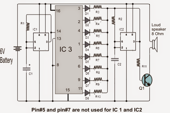
The left 555 is utilized as clock generator for the 4017 decade counter.
The operating frequency of the clock may be changed and adjusted merely by changing the value resistor R1 or by changing it with a potentiometer 50K being sure a 1K series resistor of 1K so that you can don't accidentally move the pot to short the supply with pin7 of the IC.
When the left IC 555 clock rate is varied, the speed of the 4017 output sequence is changed correspondingly which establishes the musical sounds of the box
The above output signal 555 draws the clock input of CD4017 which provides 10 active outputs (high voltage) sequentially starting with 0 and ending exit at junction 9.
As might be observed in the diagram the outputs 3 and 6 of the 4017 outputs are not utilized. This really is specially completed in order to produce spaces of silence in the melody from the music box.
Each CD4017 output could be observed feeding a series diode with a resistor which effectively links the corresponding resistor in series with the second resistor R2 555.
The above arrangement in conjunction with the capacitor C2, force the second 555 to oscillate at a particular predetermined frequency.
At any time a CD4017 output is initiated, the right hand side 555 oscillates at a frequency prefixed by the set R (of the outputs of 4017), in conjunction with R2 and C2. As soon as the whole series of the 4017 outputs are executed, the IC is reset and process is repeated.
To operate the speaker transistor Q1 has to pass the saturation cutting frequency ranges to which the second 555 is configured at.
As can be viewed, the project allows us to experience and realize a sequenced set of notes according to the preference of the user. Experimenting with the values of the resistors in series with the diodes might be smart to begin with.
You may also investigate and modify the spaces and location of the "silences", by randomly leaving or selecting from the other pins of the 4017 outputs.
The music box circuit is operated with 9 volt PP3 battery or from a 9V AC/DC adapter.
Simple Music Box circuit
Bill Of Materials for the music box circuit
- IC1 = IC2: 555 timer
- IC3: CD4017 decade counter
- Q1: TIP29 NPN bipolar transistor or the like
- R1 = R2: 33K resistor
- R3 = R5 = R9: 10K resistors
- R4 = R7 = R10: 15K resistors
- R6 = R8: 22K resistors
- R11: 470 ohm resistor
- C1: 10uF/25V
- C2: capacitor of 10nF
- D1 = D2 = D3 = D4 = D5 = D6 = D7 = D8: diode 1N4148 or equivalent
- LS: Miniature speaker 8 ohms.
The number of notes may be restricted to 10 at the most, as well as is capable of doing producing a basic chorus.
The circuit makes use of two widely used built-in circuits: The timer 555 and 4017 decade counter
Operation of the circuit of music box might be discovered given below:
The left 555 is utilized as clock generator for the 4017 decade counter.
The operating frequency of the clock may be changed and adjusted merely by changing the value resistor R1 or by changing it with a potentiometer 50K being sure a 1K series resistor of 1K so that you can don't accidentally move the pot to short the supply with pin7 of the IC.
When the left IC 555 clock rate is varied, the speed of the 4017 output sequence is changed correspondingly which establishes the musical sounds of the box
The above output signal 555 draws the clock input of CD4017 which provides 10 active outputs (high voltage) sequentially starting with 0 and ending exit at junction 9.
As might be observed in the diagram the outputs 3 and 6 of the 4017 outputs are not utilized. This really is specially completed in order to produce spaces of silence in the melody from the music box.
Each CD4017 output could be observed feeding a series diode with a resistor which effectively links the corresponding resistor in series with the second resistor R2 555.
The above arrangement in conjunction with the capacitor C2, force the second 555 to oscillate at a particular predetermined frequency.
At any time a CD4017 output is initiated, the right hand side 555 oscillates at a frequency prefixed by the set R (of the outputs of 4017), in conjunction with R2 and C2. As soon as the whole series of the 4017 outputs are executed, the IC is reset and process is repeated.
To operate the speaker transistor Q1 has to pass the saturation cutting frequency ranges to which the second 555 is configured at.
As can be viewed, the project allows us to experience and realize a sequenced set of notes according to the preference of the user. Experimenting with the values of the resistors in series with the diodes might be smart to begin with.
You may also investigate and modify the spaces and location of the "silences", by randomly leaving or selecting from the other pins of the 4017 outputs.
The music box circuit is operated with 9 volt PP3 battery or from a 9V AC/DC adapter.
Simple Music Box circuit
Bill Of Materials for the music box circuit
- IC1 = IC2: 555 timer
- IC3: CD4017 decade counter
- Q1: TIP29 NPN bipolar transistor or the like
- R1 = R2: 33K resistor
- R3 = R5 = R9: 10K resistors
- R4 = R7 = R10: 15K resistors
- R6 = R8: 22K resistors
- R11: 470 ohm resistor
- C1: 10uF/25V
- C2: capacitor of 10nF
- D1 = D2 = D3 = D4 = D5 = D6 = D7 = D8: diode 1N4148 or equivalent
- LS: Miniature speaker 8 ohms.
No comments:
Post a Comment