This content talks about regarding a basic ultrasonic remote control circuit that can be used to switch any equipment utilizing the relay in the receiver circuit.
This circuit is another one that employs ultrasonic sound waves whose frequency ranges from 40 KHz to 50 KHz.
These types of waves can’t be heard by humans as the hearing range of humans restricted to approximately 20 KHz only. These types of waves need air medium to travel unlike infrared waves that happen to be mostly used in remote controls.
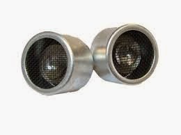
40kHz ultrasonic transducer
The offered ultrasonic remote control circuit makes use of ultrasonic transducers to generate and obtain the ultrasonic signals.
Ultrasonic transducers are utilized in measuring the distance of an object and many other functions. In this circuit, we make use of them for some other reason for producing a remote controlled relay.
Ultrasonic remote control receiver circuit


Working Of Circuit:
This project contains two parts i.e., transmitter circuit and receiver circuit.
The transmitter circuit includes a 555 timer IC that could be the heart of the circuit. Here, the 555 timer is utilized in astable multi vibrator mode. It can oscillate at a frequency of 40 - 50 KHz.
The ultrasonic transducer is employed to transmit this frequency by using ultrasonic waves. A 9v battery may be used to power the transmitter circuit. The variable resistor R3 (in transmitter circuit) may be used to adjust the frequency.
The receiver circuit includes two crucial phases for the processing of the ultrasonic waves acquired by the acquiring transducer.
The first phase is a rectifier which amplifies the signals with the aid of the transistors Q1 and Q2.
The repaired and filtered DC is given to the inverting pin of the functioning amplifier CA3140. The inverted output is employed to bias the transistor Q3 which boosts the relay and there goes the second stage.
The preset resistor R2(in receiver circuit) may be used to adjust the level of responsiveness of the circuit.
You can utilize a 9v SMPS power supply to power the receiver circuit.
The receiver circuit ought to remain ON and a push-to-on switch can be utilized in the creating circuit to serve as a remote.
Put together the circuits on common objective PCB’s. It is possible to cover the transmitter circuit in an appropriate casing and the transducer, push-to-on switch and LED ought to be outside of the casing.
Ultrasonic waves are directional in nature and therefore, you ought to guide the waves straight onto the obtaining transducer for the relay to switch on.
Parts List for the above described ultrasonic remote control circuit:
Transmitter circuit:
R1 – 18K,
R2 – 10K,
R3 – 5K variable resistor,
R4 – 1K,
C1 – 680pf,
C2 – 0.01µf,
C3 – 100µf, 25v,
L1 – green LED,
TR1 – ultrasonic transmitter,
S1 – push-to-on switch,
Receiver circuit:
R1 – 10K,
R2 – 5K variable resistor,
R3- 10K,
R4 – 15K,
R5 – 100K,
R6 – 10K,
R7 – 4.7K,
R8 – 15K,
R9 – 10K,
R10 – 12K,
R11 – 390K,
R12 – 470K,
R13 – 27K,
R14 – 1K,
C1 – 0.56µf,
C2 – 0.1µf,
C3 – 0.22µf,
C4 – 10µf, 25v,
D1, D2 – 1N4148,
D3 – 1N4007,
Q1, Q2 – BC 548,
Q3 – BC 558,
Q4 – SL 100,
RY1 – 9v relay,
RX1 – ultrasonic transmitter
This circuit is another one that employs ultrasonic sound waves whose frequency ranges from 40 KHz to 50 KHz.
These types of waves can’t be heard by humans as the hearing range of humans restricted to approximately 20 KHz only. These types of waves need air medium to travel unlike infrared waves that happen to be mostly used in remote controls.
40kHz ultrasonic transducer
The offered ultrasonic remote control circuit makes use of ultrasonic transducers to generate and obtain the ultrasonic signals.
Ultrasonic transducers are utilized in measuring the distance of an object and many other functions. In this circuit, we make use of them for some other reason for producing a remote controlled relay.
Ultrasonic remote control receiver circuit
Working Of Circuit:
This project contains two parts i.e., transmitter circuit and receiver circuit.
The transmitter circuit includes a 555 timer IC that could be the heart of the circuit. Here, the 555 timer is utilized in astable multi vibrator mode. It can oscillate at a frequency of 40 - 50 KHz.
The ultrasonic transducer is employed to transmit this frequency by using ultrasonic waves. A 9v battery may be used to power the transmitter circuit. The variable resistor R3 (in transmitter circuit) may be used to adjust the frequency.
The receiver circuit includes two crucial phases for the processing of the ultrasonic waves acquired by the acquiring transducer.
The first phase is a rectifier which amplifies the signals with the aid of the transistors Q1 and Q2.
The repaired and filtered DC is given to the inverting pin of the functioning amplifier CA3140. The inverted output is employed to bias the transistor Q3 which boosts the relay and there goes the second stage.
The preset resistor R2(in receiver circuit) may be used to adjust the level of responsiveness of the circuit.
You can utilize a 9v SMPS power supply to power the receiver circuit.
The receiver circuit ought to remain ON and a push-to-on switch can be utilized in the creating circuit to serve as a remote.
Put together the circuits on common objective PCB’s. It is possible to cover the transmitter circuit in an appropriate casing and the transducer, push-to-on switch and LED ought to be outside of the casing.
Ultrasonic waves are directional in nature and therefore, you ought to guide the waves straight onto the obtaining transducer for the relay to switch on.
Parts List for the above described ultrasonic remote control circuit:
Transmitter circuit:
R1 – 18K,
R2 – 10K,
R3 – 5K variable resistor,
R4 – 1K,
C1 – 680pf,
C2 – 0.01µf,
C3 – 100µf, 25v,
L1 – green LED,
TR1 – ultrasonic transmitter,
S1 – push-to-on switch,
Receiver circuit:
R1 – 10K,
R2 – 5K variable resistor,
R3- 10K,
R4 – 15K,
R5 – 100K,
R6 – 10K,
R7 – 4.7K,
R8 – 15K,
R9 – 10K,
R10 – 12K,
R11 – 390K,
R12 – 470K,
R13 – 27K,
R14 – 1K,
C1 – 0.56µf,
C2 – 0.1µf,
C3 – 0.22µf,
C4 – 10µf, 25v,
D1, D2 – 1N4148,
D3 – 1N4007,
Q1, Q2 – BC 548,
Q3 – BC 558,
Q4 – SL 100,
RY1 – 9v relay,
RX1 – ultrasonic transmitter
No comments:
Post a Comment