The publish describes an efficient MPPT lead acid battery charger circuit utilizing the IC bq2031 from TEXAS INSTRUMENTS.
Abstract
This sensible application article was designed specifically for the people who could very well be acquiring an MPPT-based lead acid battery charger with the help of bq2031 battery charger.
This informative article contains a structural format for charging a 12-A-hr lead acid battery using MPPT (maximum power point tracking) for enhancing charging effectiveness for photovoltaic applications.
Presentation
The simplest technique for charging a battery from a solar panel systems is usually to connect the battery directly to the solar panel, yet this might not be the most reliable method.
Assume a solar panel carries a rating of 75 W and produces a current of 4.65 A with a voltage of 16 V at regular test environment of 25 ° C temperature and 1000 W/m2 of insolation.
The lead acid battery is calculated with a voltage of 12 V; instantly hooking up the solar panel to this battery would reduce the panel voltage to 12 V and only 55.8 W (12 V and 4.65 A) could possibly be created from the panel for charging.
A DC/DC converter may be most adequately required for inexpensive charging here.
This sensible application document describes a model, working with the bq2031 for successful charging.
I-V Features of Solar Panel
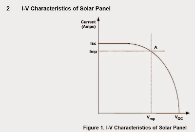
I/V feature curve of solar panel
Figure 1 exhibits the regular issues with a solar panel systems. Isc is a short-circuit current that channels by means of the panel in the event the solar panel is short circuited.
It is usually the perfect current that could be recovered from the solar panel.
Voc is the open-circuit voltage at the terminals of the solar panel.
Vmp and Imp are the voltage and current levels where optimum power can be acquired from the solar panel.
While the sunshine reduces the optimum current (Isc) which can be achieved, the highest current from the solar panel also suppresses. Figure 2 implies variation of I-V features with sun light.
The blue curve links the information of the highest power at various values of insolation
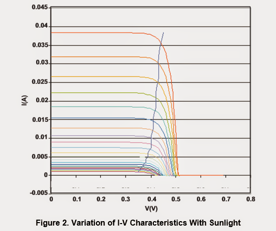
I-V variation features pertaining to sunlight
The reason behind the MPPT circuit is to make sure to maintain the functioning level of the solar panel at the highest power point in many sunshine situations.
As discovered from Figure 2, the voltage where maximum power is supplied would not alter tremendously with sunshine.
The circuit created with the bq2031 utilizes this character to incorporate MPPT.
An additional current control loop accompanies decrease the charge current as the daylight diminishes along with to maintain solar panel voltage around the maximum power point voltage.
MPPT circuit for charging lead acid batteries
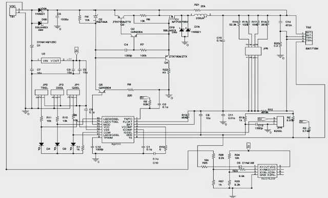
bq2031-Based MPPT Charger
Figure 3 exhibits the schematic of a DV2031S2 board with an additional current control loop put into perform the MPPT using the functional amplifier TLC27L2.
The bq2031 maintains the charging current by preserving a voltage of 250 mV at sense resistance R 20. A reference voltage of 1.565 V is established by utilizing 5 V from U2.
The input voltage is when compared with the reference voltage to generate an error voltage that is certainly executed at the SNS pin of bq2031 to reduce the charge current.
The voltage (V mp) exactly where maximum power comes available from the solar panel is conditioned employing resistors R26 and R27. V mp = 1.565(R 26 +R 27)/R 27.
With R 27 = 1 k Ω and R 26 = 9.2 k Ω, V mp = 16 V is accomplished. TLC27L2 is internally modified with a bandwidth of 6 kHz at V dd = 5 V. Simply because the bandwidth of TLC27L2 is substantially below the switching frequency of bq2031, the added current control loop remains to be continuous.
The bq2031 in the earlier circuit (Figure 3) provides an optimum current of 1 A.
In the event the solar power panel can create sufficient power to charge the battery at 1 A, the outer control loop would not move forward into action.
Nevertheless if the insulation decreases and the solar power panel strive to provide adequate energy to charge the battery at 1 A, the outer control loop diminishes the charge current to maintain input voltage at V mp.
The outcomes shown in Table 1 verify the working of the circuit. The voltage readings in assertive kind indicate the problem at any time the secondary control loop is reducing the charge current to maintain input at V mp
Abstract
This sensible application article was designed specifically for the people who could very well be acquiring an MPPT-based lead acid battery charger with the help of bq2031 battery charger.
This informative article contains a structural format for charging a 12-A-hr lead acid battery using MPPT (maximum power point tracking) for enhancing charging effectiveness for photovoltaic applications.
Presentation
The simplest technique for charging a battery from a solar panel systems is usually to connect the battery directly to the solar panel, yet this might not be the most reliable method.
Assume a solar panel carries a rating of 75 W and produces a current of 4.65 A with a voltage of 16 V at regular test environment of 25 ° C temperature and 1000 W/m2 of insolation.
The lead acid battery is calculated with a voltage of 12 V; instantly hooking up the solar panel to this battery would reduce the panel voltage to 12 V and only 55.8 W (12 V and 4.65 A) could possibly be created from the panel for charging.
A DC/DC converter may be most adequately required for inexpensive charging here.
This sensible application document describes a model, working with the bq2031 for successful charging.
I-V Features of Solar Panel
I/V feature curve of solar panel
Figure 1 exhibits the regular issues with a solar panel systems. Isc is a short-circuit current that channels by means of the panel in the event the solar panel is short circuited.
It is usually the perfect current that could be recovered from the solar panel.
Voc is the open-circuit voltage at the terminals of the solar panel.
Vmp and Imp are the voltage and current levels where optimum power can be acquired from the solar panel.
While the sunshine reduces the optimum current (Isc) which can be achieved, the highest current from the solar panel also suppresses. Figure 2 implies variation of I-V features with sun light.
The blue curve links the information of the highest power at various values of insolation
I-V variation features pertaining to sunlight
The reason behind the MPPT circuit is to make sure to maintain the functioning level of the solar panel at the highest power point in many sunshine situations.
As discovered from Figure 2, the voltage where maximum power is supplied would not alter tremendously with sunshine.
The circuit created with the bq2031 utilizes this character to incorporate MPPT.
An additional current control loop accompanies decrease the charge current as the daylight diminishes along with to maintain solar panel voltage around the maximum power point voltage.
MPPT circuit for charging lead acid batteries
bq2031-Based MPPT Charger
Figure 3 exhibits the schematic of a DV2031S2 board with an additional current control loop put into perform the MPPT using the functional amplifier TLC27L2.
The bq2031 maintains the charging current by preserving a voltage of 250 mV at sense resistance R 20. A reference voltage of 1.565 V is established by utilizing 5 V from U2.
The input voltage is when compared with the reference voltage to generate an error voltage that is certainly executed at the SNS pin of bq2031 to reduce the charge current.
The voltage (V mp) exactly where maximum power comes available from the solar panel is conditioned employing resistors R26 and R27. V mp = 1.565(R 26 +R 27)/R 27.
With R 27 = 1 k Ω and R 26 = 9.2 k Ω, V mp = 16 V is accomplished. TLC27L2 is internally modified with a bandwidth of 6 kHz at V dd = 5 V. Simply because the bandwidth of TLC27L2 is substantially below the switching frequency of bq2031, the added current control loop remains to be continuous.
The bq2031 in the earlier circuit (Figure 3) provides an optimum current of 1 A.
In the event the solar power panel can create sufficient power to charge the battery at 1 A, the outer control loop would not move forward into action.
Nevertheless if the insulation decreases and the solar power panel strive to provide adequate energy to charge the battery at 1 A, the outer control loop diminishes the charge current to maintain input voltage at V mp.
The outcomes shown in Table 1 verify the working of the circuit. The voltage readings in assertive kind indicate the problem at any time the secondary control loop is reducing the charge current to maintain input at V mp
No comments:
Post a Comment