By presenting the above demonstrated circuit between the lamp along with the supply, the proposed blown brake light bulb indicator may be very easily developed and used in almost any vehicle.
The working is pretty uncomplicated:
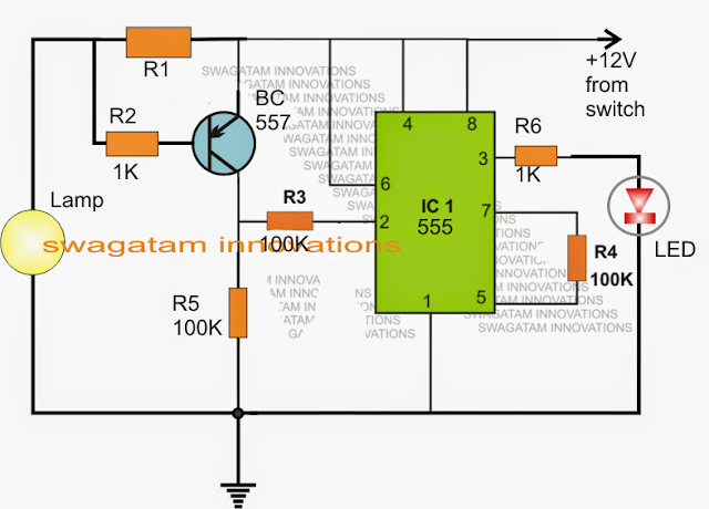
The IC 555 is configured as a simple voltage comparator, where its pin2 evolves into the sensing input.
The BC557 in addition to the connected R1, R2 resistors forms a current to voltage converter stage.
Provided that a working bulb lamp remains linked across the demonstrated points, a small negative potential corresponding to the bulb current consumption is created across Rx.
This potential turns into adequate to maintain the BC557 activated and executing which often maintains pin2 of the IC high.
With the above circumstances, pin3 of the IC stays low and the LED remains to be turn off.
Nevertheless in an event the car bulb fuses or prevents illuminating, the potential across Rx disappears or decreases to an level where the BC557 simply prevents carrying out.
This promptly makes pin2 of the IC high along with the LED starts glowing suggesting the blown brake light bulb situation to the user.
The above design may be as well successfully utilized in a number of functions which need some type of current (amp) checking for example an over-current or over-load cut off etc.
R1 might be determined given below:
R1 = 0.7/bulb current rating
The above described circuit may be a lot less complicated by means of the following cofiguration:
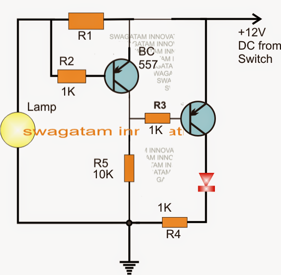
The working is pretty uncomplicated:
The IC 555 is configured as a simple voltage comparator, where its pin2 evolves into the sensing input.
The BC557 in addition to the connected R1, R2 resistors forms a current to voltage converter stage.
Provided that a working bulb lamp remains linked across the demonstrated points, a small negative potential corresponding to the bulb current consumption is created across Rx.
This potential turns into adequate to maintain the BC557 activated and executing which often maintains pin2 of the IC high.
With the above circumstances, pin3 of the IC stays low and the LED remains to be turn off.
Nevertheless in an event the car bulb fuses or prevents illuminating, the potential across Rx disappears or decreases to an level where the BC557 simply prevents carrying out.
This promptly makes pin2 of the IC high along with the LED starts glowing suggesting the blown brake light bulb situation to the user.
The above design may be as well successfully utilized in a number of functions which need some type of current (amp) checking for example an over-current or over-load cut off etc.
R1 might be determined given below:
R1 = 0.7/bulb current rating
The above described circuit may be a lot less complicated by means of the following cofiguration:
Thanks for share your blog here
ReplyDeleteD1s Xenon lyspære