LEDs are a lot economical compared to ordinary incandescent lamps or perhaps the advanced halogen lamps with regards to their effectiveness, luminance and life.
Consequently even in automotive field we are able to now experience a swift transition from the old filament kind of bulbs to the latest high bright LED lamps.
However these are usually being executed as brake lights and head lights in most modern and the new generation vehicles.
In the suggested automotive brake light circuit 1 watt high efficiency LEDs are being used for performing the extremely high strength of illumination.
Everyone knows that essentially today's almost all latest high watt LEDs need two essential guidelines to be able to work properly and safely, specifically a current controlled supply and thermal or heat managed assembly.
The first criterion may be executed by utilizing any specific modern advanced linear IC for example a LM338, I have mentioned it elaborately in one of my earlier content high watt LED current limiter circuit.
For the second condition one can basically use a special aluminum base PCB installed on a heatsink for assembling the 1 watt LEDs.
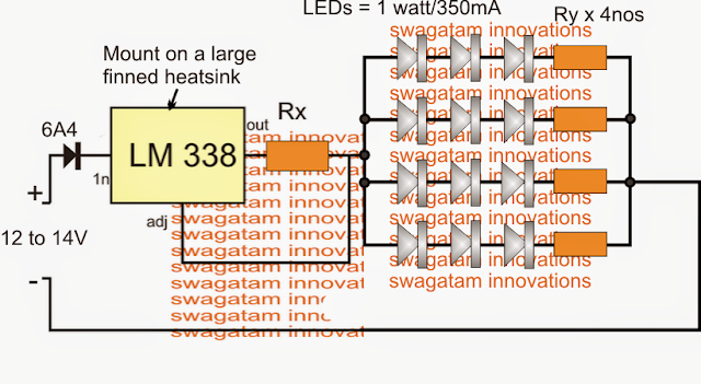
automotive LED brake light circuit utilizing 1 watt high efficiency LEDs
The circuit for the LED brake light might be observed above, and it appears pretty straightforward.
The LM338 is set up as a current limiter, where Rx decides the highest permitted amps to the linked LEDs. It might be determined by utilizing the following formula:
Rx = 1.25/LED current
When LeDs are linked in series there effective current intake is actually equivalent to the rating of the one individual LED. Consequently in the diagram each string might utilize 350mA since this is exactly the rating of each 1 watt LED.
Joined current for all the three strings could be 3 x 350mA = 1050mA or around 1 amp
Substituting the above parameter in the formula we have:
Rx = 1.25/1 = 1.25 Ohms
Wattage = 1.25 x 1 = 1.25 watts
The resistors Ry which is often observed linked in series with the LEDs are in fact optional, these might be incorporated only for helping the IC and offering appropriate balance across the LED strings.
It might be determined utilizing the following formula:
Ry = (Supply - LED total FWD voltage) / LED current
Since here the LEDs are specified with a forward voltage of 3.3V and 3 nos are organized in the sequence, the combined forward voltage turns into 3 x 3.3 = 9.9V
For reducing full loading of the LEDs, we are able to obtain the current at 300mA rather than the stipulated 350mA
Consequently Ry = (13 - 9.9) / 0.3 = 10.33 ohms or simply 10 Ohms
wattage = (13 - 9.9) x 0.3 = 0.93 watts or 1 watt
It appears to be we skipped a significant inclusion in the above diagram, it's the dimmed LED feature throughout the regular course of the vehicle and while the brakes are not utilized.
The following diagram indicates how basically this might be executed utilizing a identical linked resistor Rz, with Rx.

LED brake light circuit dimming when vehicle is functioning without brakes
Here the values of the Rx and Rz might be alike however two times that of the above determined value that is 1.25 x 2 = 2.5 Ohms. This could permit a 50% dimming of the tail lights while the brakes are in the released position.
If one wishes to acquire further dimming of the LEDs Rx might be increased to 3 ohms or 3.5 Ohms, this could also mean lowering the Rz value proportionately such that the parallel value of the two resistors constitutes 1.25 Ohms.
Consequently even in automotive field we are able to now experience a swift transition from the old filament kind of bulbs to the latest high bright LED lamps.
However these are usually being executed as brake lights and head lights in most modern and the new generation vehicles.
In the suggested automotive brake light circuit 1 watt high efficiency LEDs are being used for performing the extremely high strength of illumination.
Everyone knows that essentially today's almost all latest high watt LEDs need two essential guidelines to be able to work properly and safely, specifically a current controlled supply and thermal or heat managed assembly.
The first criterion may be executed by utilizing any specific modern advanced linear IC for example a LM338, I have mentioned it elaborately in one of my earlier content high watt LED current limiter circuit.
For the second condition one can basically use a special aluminum base PCB installed on a heatsink for assembling the 1 watt LEDs.
automotive LED brake light circuit utilizing 1 watt high efficiency LEDs
The circuit for the LED brake light might be observed above, and it appears pretty straightforward.
The LM338 is set up as a current limiter, where Rx decides the highest permitted amps to the linked LEDs. It might be determined by utilizing the following formula:
Rx = 1.25/LED current
When LeDs are linked in series there effective current intake is actually equivalent to the rating of the one individual LED. Consequently in the diagram each string might utilize 350mA since this is exactly the rating of each 1 watt LED.
Joined current for all the three strings could be 3 x 350mA = 1050mA or around 1 amp
Substituting the above parameter in the formula we have:
Rx = 1.25/1 = 1.25 Ohms
Wattage = 1.25 x 1 = 1.25 watts
The resistors Ry which is often observed linked in series with the LEDs are in fact optional, these might be incorporated only for helping the IC and offering appropriate balance across the LED strings.
It might be determined utilizing the following formula:
Ry = (Supply - LED total FWD voltage) / LED current
Since here the LEDs are specified with a forward voltage of 3.3V and 3 nos are organized in the sequence, the combined forward voltage turns into 3 x 3.3 = 9.9V
For reducing full loading of the LEDs, we are able to obtain the current at 300mA rather than the stipulated 350mA
Consequently Ry = (13 - 9.9) / 0.3 = 10.33 ohms or simply 10 Ohms
wattage = (13 - 9.9) x 0.3 = 0.93 watts or 1 watt
It appears to be we skipped a significant inclusion in the above diagram, it's the dimmed LED feature throughout the regular course of the vehicle and while the brakes are not utilized.
The following diagram indicates how basically this might be executed utilizing a identical linked resistor Rz, with Rx.
LED brake light circuit dimming when vehicle is functioning without brakes
Here the values of the Rx and Rz might be alike however two times that of the above determined value that is 1.25 x 2 = 2.5 Ohms. This could permit a 50% dimming of the tail lights while the brakes are in the released position.
If one wishes to acquire further dimming of the LEDs Rx might be increased to 3 ohms or 3.5 Ohms, this could also mean lowering the Rz value proportionately such that the parallel value of the two resistors constitutes 1.25 Ohms.
No comments:
Post a Comment